Generating Mipmaps
Introduction
Our program can now load and render 3D models. In this chapter, we will add one more feature, mipmap generation. Mipmaps are widely used in games and rendering software, and Vulkan gives us complete control over how they are created.
Mipmaps are precalculated, downscaled versions of an image. Each new image is half the width and height of the previous one. Mipmaps are used as a form of Level of Detail or LOD. Objects that are far away from the camera will sample their textures from the smaller mip images. Using smaller images increases the rendering speed and avoids artifacts such as Moiré patterns. An example of what mipmaps look like:
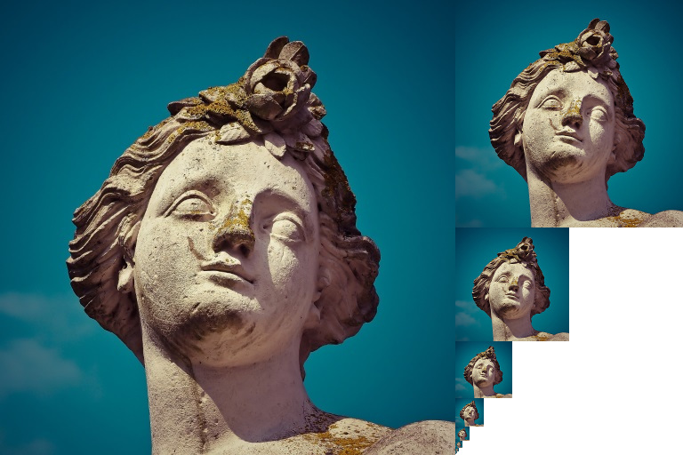
Image creation
In Vulkan, each of the mip images is stored in different mip levels of a vk::Image.
Mip level 0 is the original image, and the mip levels after level 0 are commonly referred to as the mip chain.
The number of mip levels is specified when the vk::Image is created.
Up until now, we have always set this value to one.
We need to calculate the number of mip levels from the dimensions of the image.
First, add a class member to store this number:
...
uint32_t               mipLevels          = 0;
vk::raii::Image        textureImage       = nullptr;
...
The value for mipLevels can be found once we’ve loaded the texture in createTextureImage:
int            texWidth, texHeight, texChannels;
stbi_uc       *pixels    = stbi_load(TEXTURE_PATH.c_str(), &texWidth, &texHeight, &texChannels, STBI_rgb_alpha);
...
mipLevels = static_cast<uint32_t>(std::floor(std::log2(std::max(texWidth, texHeight)))) + 1;
This calculates the number of levels in the mip chain.
The max function selects the largest dimension.
The log2 function calculates how many times that dimension can be divided by 2.
The floor function handles cases where the largest dimension is not a power of 2.
1 is added so that the original image has a mip level.
To use this value, we need to change the createImage, createImageView, and transitionImageLayout functions to allow us to specify the number of mip levels.
Add a mipLevels parameter to the functions:
std::pair<vk::raii::Image, vk::raii::DeviceMemory>
    createImage(uint32_t                width,
                uint32_t                height,
                uint32_t                mipLevels,
                vk::Format              format,
                vk::ImageTiling         tiling,
                vk::ImageUsageFlags     usage,
                vk::MemoryPropertyFlags properties)
{
    vk::ImageCreateInfo imageInfo{.imageType     = vk::ImageType::e2D,
                                  .format        = format,
                                  .extent        = {width, height, 1},
                                  .mipLevels     = mipLevels,
    ...
}
vk::raii::ImageView createImageView(vk::Image const &image, vk::Format format, vk::ImageAspectFlags aspectFlags, uint32_t mipLevels) const
{
vk::ImageViewCreateInfo viewInfo{
.image = image,
.viewType = vk::ImageViewType::e2D,
.format = format,
.subresourceRange = {.aspectMask = aspectFlags, .levelCount = mipLevels, .layerCount = 1}};
...
}void transitionImageLayout(
vk::raii::CommandBuffer &commandBuffer, vk::raii::Image const &image, vk::ImageLayout oldLayout, vk::ImageLayout newLayout, uint32_t mipLevels)
{
vk::ImageMemoryBarrier barrier{.oldLayout = oldLayout,
.newLayout = newLayout,
.srcQueueFamilyIndex = vk::QueueFamilyIgnored,
.dstQueueFamilyIndex = vk::QueueFamilyIgnored,
.image = image,
.subresourceRange = {.aspectMask = vk::ImageAspectFlagBits::eColor, .levelCount = mipLevels, .layerCount = 1}};
...Update all calls to these functions to use the right values:
std::tie(depthImage, depthImageMemory) = createImage(swapChainExtent.width,
                                                     swapChainExtent.height,
                                                     1,
                                                     depthFormat,
                                                     vk::ImageTiling::eOptimal,
                                                     vk::ImageUsageFlagBits::eDepthStencilAttachment,
                                                     vk::MemoryPropertyFlagBits::eDeviceLocal);
...
std::tie(textureImage, textureImageMemory) =
    createImage(texWidth,
                texHeight,
                mipLevels,
                vk::Format::eR8G8B8A8Srgb,
                vk::ImageTiling::eOptimal,
                vk::ImageUsageFlagBits::eTransferSrc | vk::ImageUsageFlagBits::eTransferDst | vk::ImageUsageFlagBits::eSampled,
                vk::MemoryPropertyFlagBits::eDeviceLocal);
swapChainImageViews.emplace_back(createImageView(image, swapChainSurfaceFormat.format, vk::ImageAspectFlagBits::eColor, 1));
...
depthImageView = createImageView(depthImage, depthFormat, vk::ImageAspectFlagBits::eDepth, 1);
...
textureImageView = createImageView(*textureImage, vk::Format::eR8G8B8A8Srgb, vk::ImageAspectFlagBits::eColor, mipLevels);In the previous chapter, createTextureImage called beginSingleTimeCommands and
endSingleTimeCommands three separate times: once around the layout transition, once around the
buffer-to-image copy, and once around the final transition to shader-read layout. Generating
mipmaps adds a blit and two more layout transitions for every mip level, and opening a new command
buffer for each of those would be wasteful. So instead, createTextureImage will call
beginSingleTimeCommands once at the start, record the transition, the copy, and all of
generateMipmaps into that same command buffer, and only call endSingleTimeCommands once, at
the very end. beginSingleTimeCommands and endSingleTimeCommands themselves haven’t changed -
we’re just calling them less often:
vk::raii::CommandBuffer commandBuffer = beginSingleTimeCommands();
transitionImageLayout(commandBuffer, textureImage, vk::ImageLayout::eUndefined, vk::ImageLayout::eTransferDstOptimal, mipLevels);
Generating Mipmaps
Our texture image now has multiple mip levels, but the staging buffer can only be used to fill mip level 0.
The other levels are still undefined.
To fill these levels, we need to generate the data from the single level that we have.
We will use the vk::raii::CommandBuffer::blitImage command.
This command performs copying, scaling, and filtering operations.
We will call this multiple times to blit data to each level of our texture image.
vk::raii::CommandBuffer::blitImage is considered a transfer operation, so we must inform Vulkan that we intend to use the texture image as both the source and destination of a transfer.
Add vk::ImageUsageFlagBits::eTransferSrc to the texture image’s usage flags in createTextureImage:
...
std::tie(textureImage, textureImageMemory) =
    createImage(texWidth,
                texHeight,
                mipLevels,
                vk::Format::eR8G8B8A8Srgb,
                vk::ImageTiling::eOptimal,
                vk::ImageUsageFlagBits::eTransferSrc | vk::ImageUsageFlagBits::eTransferDst | vk::ImageUsageFlagBits::eSampled,
                vk::MemoryPropertyFlagBits::eDeviceLocal);
...
Like other image operations, vk::raii::CommandBuffer::blitImage depends on the layout of the image it operates on.
We could transition the entire image to vk::ImageLayout::eGeneral, but this will most likely be slow.
For optimal performance, the source image should be in vk::ImageLayout::eTransferSrcOptimal and the destination image should be in vk::ImageLayout::eTransferDstOptimal.
Vulkan allows us to transition each mip level of an image independently.
Each blit will only deal with two mip levels at a time, so we can transition each level into the optimal layout between blits commands.
transitionImageLayout only performs layout transitions on the entire image, so we’ll need to write a few more pipeline barrier commands.
Remove the existing transition to vk::ImageLayout::eShaderReadOnlyOptimal in createTextureImage:
...
transitionImageLayout(commandBuffer, textureImage, vk::ImageLayout::eUndefined, vk::ImageLayout::eTransferDstOptimal, mipLevels);
copyBufferToImage(commandBuffer, stagingBuffer, textureImage, static_cast<uint32_t>(texWidth), static_cast<uint32_t>(texHeight));
//transitioned to vk::ImageLayout::eShaderReadOnlyOptimal while generating mipmaps
...
This will leave each level of the texture image in vk::ImageLayout::eTransferDstOptimal.
Each level will be transitioned to vk::ImageLayout::eShaderReadOnlyOptimal after the blit command reading from it is finished.
We’re now going to write the function that generates the mipmaps:
void generateMipmaps(vk::raii::CommandBuffer &commandBuffer,
                     vk::raii::Image         &image,
                     int32_t                  texWidth,
                     int32_t                  texHeight,
                     uint32_t                 mipLevels)
{
		vk::ImageMemoryBarrier barrier = {.srcAccessMask       = vk::AccessFlagBits::eTransferWrite,
		                                  .dstAccessMask       = vk::AccessFlagBits::eTransferRead,
		                                  .oldLayout           = vk::ImageLayout::eTransferDstOptimal,
		                                  .newLayout           = vk::ImageLayout::eTransferSrcOptimal,
		                                  .srcQueueFamilyIndex = vk::QueueFamilyIgnored,
		                                  .dstQueueFamilyIndex = vk::QueueFamilyIgnored,
		                                  .image               = image,
										  .subresourceRange    = {.aspectMask = vk::ImageAspectFlagBits::eColor, .levelCount = 1, .layerCount = 1}};
}
We’re going to make several transitions, so we’ll reuse this vk::ImageMemoryBarrier.
The fields set above will remain the same for all barriers.
subresourceRange.miplevel, oldLayout, newLayout, srcAccessMask, and dstAccessMask will be changed for each transition.
int32_t mipWidth  = texWidth;
int32_t mipHeight = texHeight;

for (uint32_t i = 1; i < mipLevels; i++)
{
}
This loop will record each of the vk::raii::CommandBuffer::blitImage commands.
Note that the loop variable starts at 1, not 0.
barrier.subresourceRange.baseMipLevel = i - 1;
barrier.oldLayout                     = vk::ImageLayout::eTransferDstOptimal;
barrier.newLayout                     = vk::ImageLayout::eTransferSrcOptimal;
barrier.srcAccessMask                 = vk::AccessFlagBits::eTransferWrite;
barrier.dstAccessMask                 = vk::AccessFlagBits::eTransferRead;

commandBuffer.pipelineBarrier(vk::PipelineStageFlagBits::eTransfer, vk::PipelineStageFlagBits::eTransfer, {}, {}, {}, barrier);
First, we transition level i - 1 to vk::ImageLayout::eTransferSrcOptimal.
This transition will wait for level i - 1 to be filled, either from the previous blit command, or from vk::raii::CommandBuffer::copyBufferToImage.
The current blit command will wait on this transition.
vk::ImageBlit blit = {.srcSubresource = {.aspectMask = vk::ImageAspectFlagBits::eColor, .mipLevel = i - 1, .layerCount = 1},
                      .srcOffsets     = std::array<vk::Offset3D, 2>({{}, {mipWidth, mipHeight, 1}}),
                      .dstSubresource = {.aspectMask = vk::ImageAspectFlagBits::eColor, .mipLevel = i, .layerCount = 1},
                      .dstOffsets     = std::array<vk::Offset3D, 2>({{}, {1 < mipWidth ? mipWidth / 2 : 1, 1 < mipHeight ? mipHeight / 2 : 1, 1}})};
Next, we specify the regions that will be used in the blit operation.
The source mip level is i - 1 and the destination mip level is i.
The two elements of the srcOffsets array determine the 3D region that data will be blitted from.
dstOffsets determines the region that data will be blitted to.
The X and Y dimensions of the dstOffsets[1] are divided by two since each mip level is half the size of the previous level.
The Z dimension of srcOffsets[1] and dstOffsets[1] must be 1, since a 2D image has a depth of 1.
commandBuffer.blitImage(image, vk::ImageLayout::eTransferSrcOptimal, image, vk::ImageLayout::eTransferDstOptimal, blit, vk::Filter::eLinear);Now, we record the blit command.
Note that image is used for both the srcImage and dstImage parameter.
This is because we’re blitting between different levels of the same image.
The source mip level was just transitioned to vk::ImageLayout::eTransferSrcOptimal and the destination level is still in vk::ImageLayout::eTransferDstOptimal from createTextureImage.
Beware if you are using a dedicated transfer queue (as suggested in Vertex buffers): vk::raii::CommandBuffer::blitImage must be submitted to a queue with graphics capability.
The last parameter allows us to specify a vk::Filter to use in the blit.
We have the same filtering options here that we had when making the vk::raii::Sampler.
We use the vk::Filter::eLinear to enable interpolation.
barrier.oldLayout     = vk::ImageLayout::eTransferSrcOptimal;
barrier.newLayout     = vk::ImageLayout::eShaderReadOnlyOptimal;
barrier.srcAccessMask = vk::AccessFlagBits::eTransferRead;
barrier.dstAccessMask = vk::AccessFlagBits::eShaderRead;

commandBuffer.pipelineBarrier(vk::PipelineStageFlagBits::eTransfer, vk::PipelineStageFlagBits::eFragmentShader, {}, {}, {}, barrier);
This barrier transitions mip level i - 1 to vk::ImageLayout::eShaderReadOnlyOptimal.
This transition waits on the current blit command to finish.
All sampling operations will wait on this transition to finish.
    ...
    if (1 < mipWidth)
    {
      mipWidth /= 2;
    }
    if (1 < mipHeight)
    {
      mipHeight /= 2;
    }
}
At the end of the loop, we divide the current mip dimensions by two. We check each dimension before the division to ensure that dimension never becomes 0. This handles cases where the image is not square, since one of the mip dimensions would reach 1 before the other dimension. When this happens, that dimension should remain 1 for all remaining levels.
		barrier.subresourceRange.baseMipLevel = mipLevels - 1;
		barrier.oldLayout                     = vk::ImageLayout::eTransferDstOptimal;
		barrier.newLayout                     = vk::ImageLayout::eShaderReadOnlyOptimal;
		barrier.srcAccessMask                 = vk::AccessFlagBits::eTransferWrite;
		barrier.dstAccessMask                 = vk::AccessFlagBits::eShaderRead;

		commandBuffer.pipelineBarrier(vk::PipelineStageFlagBits::eTransfer, vk::PipelineStageFlagBits::eFragmentShader, {}, {}, {}, barrier);
}
Finally, we insert one more pipeline barrier.
This barrier transitions the last mip level from vk::ImageLayout::eTransferDstOptimal to vk::ImageLayout::eShaderReadOnlyOptimal.
The loop didn’t handle this, since the last mip level is never blitted from.
Finally, add the call to generateMipmaps in createTextureImage, and end the single-time
command buffer we opened at the start of this chapter now that every operation has been recorded
into it:
transitionImageLayout(commandBuffer, textureImage, vk::ImageLayout::eUndefined, vk::ImageLayout::eTransferDstOptimal, mipLevels);
copyBufferToImage(commandBuffer, stagingBuffer, textureImage, static_cast<uint32_t>(texWidth), static_cast<uint32_t>(texHeight));
//transitioned to vk::ImageLayout::eShaderReadOnlyOptimal while generating mipmaps
generateMipmaps(commandBuffer, textureImage, texWidth, texHeight, mipLevels);
endSingleTimeCommands(std::move(commandBuffer));
Our texture image’s mipmaps are now filled.
Linear filtering support
It is very convenient to use a built-in function like vk::raii::CommandBuffer::blitImage to generate all the mip levels, but unfortunately it is not guaranteed to be supported on all platforms.
It requires the texture image format we use to support linear filtering, which can be checked with the vk::raii::PhysicalDevice::getFormatProperties function.
We will add a check to the generateMipmaps function for this.
First, add a parameter that specifies the image format:
void createTextureImage()
{
    ...
    generateMipmaps(commandBuffer, textureImage, vk::Format::eR8G8B8A8Srgb, texWidth, texHeight, mipLevels);
}

void generateMipmaps(vk::raii::CommandBuffer &commandBuffer,
                     vk::raii::Image         &image,
                     vk::Format               imageFormat,
                     int32_t                  texWidth,
                     int32_t                  texHeight,
                     uint32_t                 mipLevels)
{
    ...
}
In the generateMipmaps function, use vk::raii::PhysicalDevice::getFormatProperties to request the properties of the texture image format:
void generateMipmaps(vk::raii::CommandBuffer &commandBuffer,
                     vk::raii::Image         &image,
                     vk::Format               imageFormat,
                     int32_t                  texWidth,
                     int32_t                  texHeight,
                     uint32_t                 mipLevels)
{
    // Check if image format supports linear blit-ing
    vk::FormatProperties formatProperties = physicalDevice->getFormatProperties(imageFormat);
    ...
The vk::FormatProperties struct has three fields named linearTilingFeatures, optimalTilingFeatures and bufferFeatures that each describe how the format can be used depending on the way it is used.
We create a texture image with the optimal tiling format, so we need to check optimalTilingFeatures.
Support for the linear filtering feature can be checked with the vk::FormatFeatureFlagBits::eSampledImageFilterLinear:
if (!(formatProperties.optimalTilingFeatures & vk::FormatFeatureFlagBits::eSampledImageFilterLinear))
{
  throw std::runtime_error("texture image format does not support linear blitting!");
}
There are two alternatives in this case. You could implement a function that searches common texture image formats for one that does support linear blitting, or you could implement the mipmap generation in software with a library like stb_image_resize. Each mip level can then be loaded into the image in the same way that you loaded the original image.
It should be noted that it is uncommon in practice to generate the mipmap levels at runtime anyway. Usually they are pre-generated and stored in the texture file alongside the base level to improve loading speed. Implementing resizing in software and loading multiple levels from a file is left as an exercise to the reader.
Sampler
While the vk::raii::Image holds the mipmap data, vk::raii::Sampler controls how that data is read while rendering.
Vulkan allows us to specify minLod, maxLod, mipLodBias, and mipmapMode ("Lod" means "Level of Detail").
When a texture is sampled, the sampler selects a mip level according to the following pseudocode:
lod = getLodLevelFromScreenSize(); //smaller when the object is close, may be negative
lod = clamp(lod + mipLodBias, minLod, maxLod);

level = clamp(floor(lod), 0, texture.mipLevels - 1);  //clamped to the number of mip levels in the texture

if (mipmapMode == vk::SamplerMipmapMode::eNearest)
{
    color = sample(level);
}
else
{
    color = blend(sample(level), sample(level + 1));
}
If samplerInfo.mipmapMode is vk::SamplerMipmapMode::eNearest, lod selects the mip level to sample from.
If the mipmap mode is vk::SamplerMipmapMode::eLinear, lod is used to select two mip levels to be sampled.
Those levels are sampled and the results are linearly blended.
The sample operation is also affected by lod:
if (lod <= 0)
{
    color = readTexture(uv, magFilter);
}
else
{
    color = readTexture(uv, minFilter);
}
If the object is close to the camera, magFilter is used as the filter.
If the object is further from the camera, minFilter is used.
Normally, lod is non-negative, and is only 0 when close the camera.
mipLodBias lets us force Vulkan to use lower lod and level than it would normally use.
To see the results of this chapter, we need to choose values for our textureSampler.
We’ve already set the minFilter and magFilter to use vk::Filter::eLinear.
We just need to choose values for minLod, maxLod, mipLodBias, and mipmapMode.
void createTextureSampler()
{
    vk::PhysicalDeviceProperties properties = physicalDevice.getProperties();
		vk::SamplerCreateInfo        samplerInfo{
		    .magFilter        = vk::Filter::eLinear,
		    .minFilter        = vk::Filter::eLinear,
		    .mipmapMode       = vk::SamplerMipmapMode::eLinear,
		    .addressModeU     = vk::SamplerAddressMode::eRepeat,
		    .addressModeV     = vk::SamplerAddressMode::eRepeat,
		    .addressModeW     = vk::SamplerAddressMode::eRepeat,
		    .mipLodBias       = 0.0f,
		    .anisotropyEnable = vk::True,
		    .maxAnisotropy    = properties.limits.maxSamplerAnisotropy,
		    .compareEnable    = vk::False,
		    .compareOp        = vk::CompareOp::eAlways,
		    .minLod           = 0.0f,
		    .maxLod           = vk::LodClampNone};
    ...
}
In the code above, we’ve set up the sampler with linear filtering for both minification and magnification, and linear interpolation between mip levels. We’ve also set the mip level bias to 0.0f.
The minLod and maxLod are used to effectively set the range of mip levels to be used by clamping the minimum and maximum LOD values. By setting minLod to 0.0f and maxLod to vk::LodClampNone we ensure the full range of mip levels will be used.
Now run your program, and you should see the following:
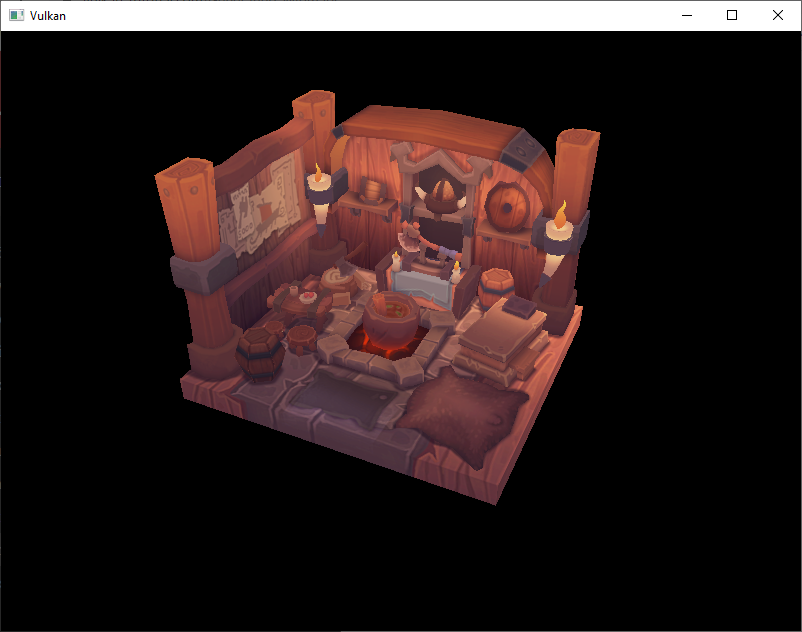
It’s not a dramatic difference, since our scene is so simple. There are subtle differences if you look close.
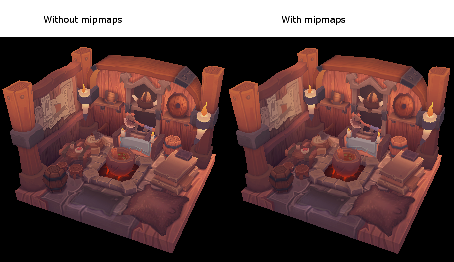
The most noticeable difference is the writing in the papers. With mipmaps, the writing has been smoothed. Without mipmaps, the writing has harsh edges and gaps from Moiré artifacts.
You can play around with the sampler settings to see how they affect mipmapping.
For example, by changing minLod, you can force the sampler to not use the lowest mip levels:
samplerInfo.minLod = static_cast<float>(mipLevels / 2);These settings will produce this image:
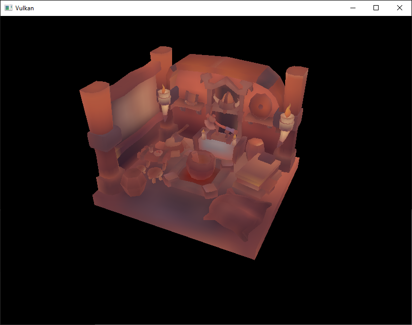
This is how higher mip levels will be used when objects are further away from the camera.
The next chapter will walk us through multisampling to produce a smoother image.